
Lab notes #3: from breadboard to brain
A guided tour of the bench as it really is, what every part does, the firmware module by module, the plug-in port idea, and the safety rules we refuse to bend.

In lab notes #1 we promised you the mess. Here it is, sort of. The real bench is a plywood board covered in jumper wires, a jar of probes and a seedling that has seen things. Photos are coming once the wiring is presentable enough not to frighten anyone. For now, here's the bench as a blueprint, which is a polite way of saying "a drawing that hides the coffee rings."
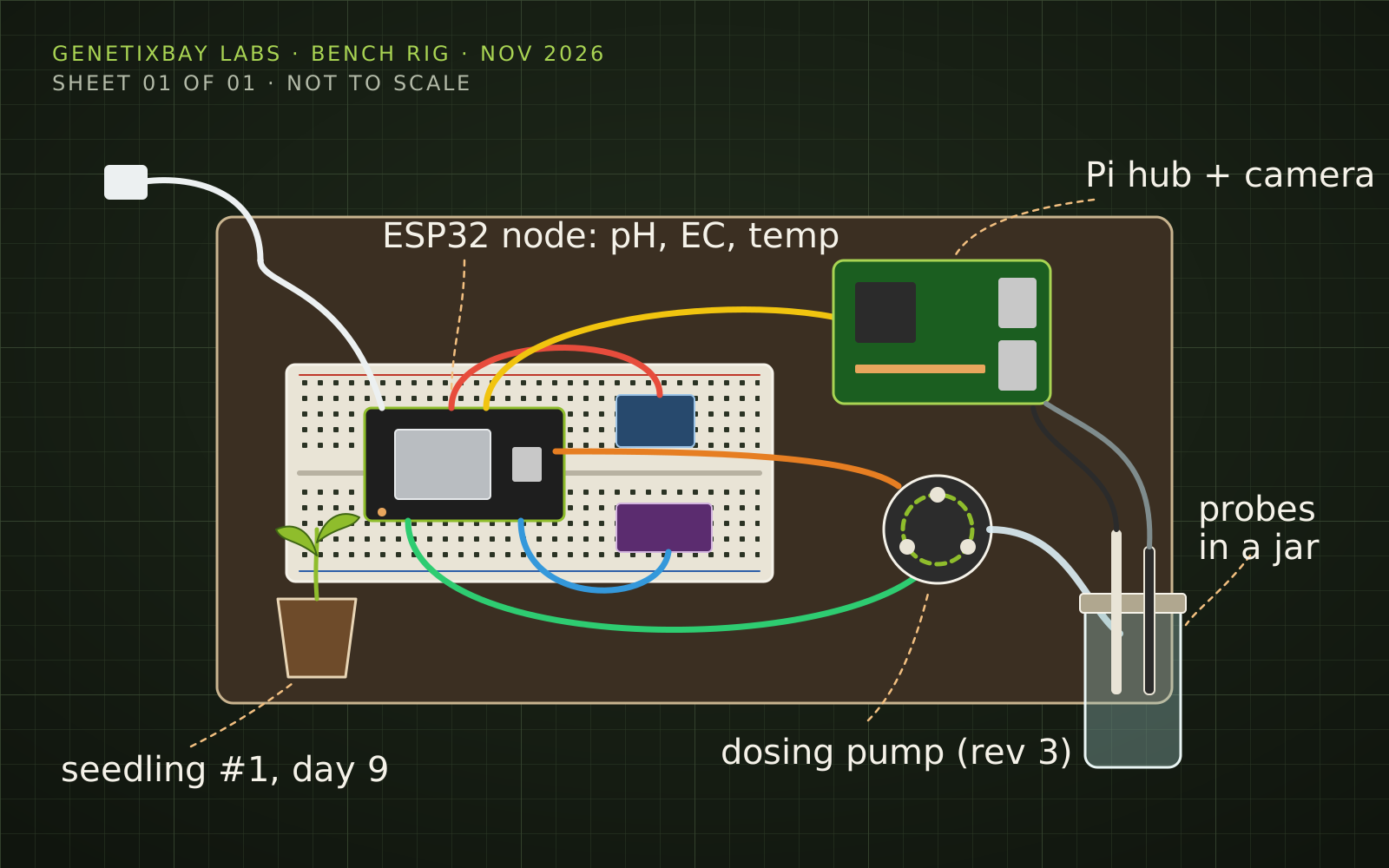
What each part does
Everything on the bench has one job. Most of them have a backup job: telling us when another part is lying.
| Part | Its job | Why it matters |
|---|---|---|
| ESP32 node | The brain of the root zone. Reads every sensor, runs every pump | Cheap, fast, Wi-Fi built in, and it keeps working when the Wi-Fi doesn't |
| pH probe and board | Measures how acidic the nutrient solution is | Its board can swing up to 5 V, so it goes through a voltage divider before it can cook a 3.3 V pin |
| EC probe and board | Measures how much fertiliser is dissolved (EC, shown as ppm too) | Switched off between readings so it doesn't fight the pH probe in the same water |
| Waterproof temperature probe | Reservoir water temperature | EC readings need it, and warm water holds less oxygen |
| Air sensors | Air temperature, humidity and an air-quality estimate | Feeds the exhaust fan and the VPD maths. The CO₂ number is labelled as an estimate, because it is one |
| Four load cells and a 24-bit converter | Weigh the reservoir, like a bathroom scale | How much the plants drank, whether something leaks, and whether a dose really happened |
| Two flow sensors | Count pulses as water moves | Proof that water went where the pump said it went |
| 8-channel relay board | Switches the 12 V pumps, valves and dosers | 12 V DC only. Never mains. More on that below |
| Peristaltic dosing pumps | Push measured amounts of nutrient and pH Down | Rev 3. Revs 1 and 2 are in the drawer of shame |
| Pressure tank and transducer | Store and measure the high-pressure mist side | Lets a small pump fire every nozzle at full pressure |
| Hub computer and camera | Plans, history, photos, your phone | Optional for safety. The node never waits for it |
The node never waits for the hub. If the hub, the Wi-Fi or the cloud disappears, the readings keep flowing in, the outputs keep switching, and the safety layer can still cut the pump power by itself.
The firmware, module by module
The node runs one firmware for three grow methods, picked with a single setting: hpa for high-pressure aeroponics, dwc for deep water culture, and drip for soil and coco. Inside, it's split into small tasks that each do one thing and report in.
- Safety runs at the top priority, ten times a second. It owns the watchdog, watches the leak rope, the e-stop and the float switches, checks for overpressure, and notices if the reservoir gets lighter while nothing is supposed to be running. That last one is how you catch a leak before your downstairs neighbour does.
- Relays start latched off before the pins even become outputs, so a reboot can't twitch a pump. Every role has a maximum on-time. Some things are interlocked: misting zones never open together, and dosers never run while the top-off does, so every weight change has exactly one suspect.
- Dosing follows the same five steps every time: dose, check the weight change, mix, let it settle, then measure. Each pump has a per-dose cap and a rolling 24-hour cap, and those totals survive a reboot.
- Mist is the aeroponics scheduler, with day and night intervals and a pressure loop. Its settings are saved on the node and it needs no network. After a reboot, the first thing it does is mist.
- Drip runs up to four zones by timer, pot weight or soil moisture, and keeps track of runoff.
- Climate ramps the lights at sunrise and sunset and drives the exhaust fan from temperature and VPD.
- Sense reads everything and stamps each value as valid and fresh. A stale or nonsense reading blocks automatic dosing instead of being trusted.
- Telemetry prints one line of readings every five seconds and can send it to the hub. Misting and safety never wait on it.
Status, honestly: this is bench firmware, version 0.2.0. It builds cleanly for three board types. It has not run on real hardware yet. Next, it meets the breadboard one subsystem at a time, starting with the relays and a multimeter, and we'll tell you what catches fire. Figuratively. Hopefully.
The plug-in port idea
Here's the part we're most excited about. The finished node won't have a rat's nest of screw terminals. It'll have a row of labelled, sealed ports: PROBE 1, PROBE 2, PRESS, FLOW, WEIGHT, I2C, 1-WIRE, SOIL, 12 V OUT and so on. You plug a sensor in, and the node works out what it is.
- Probes carry a tiny ID. Each sensor plug has one resistor inside it, and its value says what's on the other end: 1 kΩ means pH, 2.2 kΩ means EC, 22 kΩ means a pressure sensor. The node reads the voltage and labels the port.
- Digital sensors introduce themselves. The node scans the I²C bus and the 1-Wire line and names whatever answers.
- Pumps can't go in sensor ports. The 12 V outputs use a different connector family entirely, so a 6 A pump physically can't be plugged into a probe socket at 2 a.m. We've all been that tired.
On the bench today, "plug and play" means a sticky note that says "PROBE 1 = pH, DON'T". The firmware for port detection is already written, though.
Safety rules we don't bend
High-pressure aeroponics is the least forgiving way to grow, and water and electricity are not friends. So the rules come first, before any clever feature.
- The relay boards switch 12 V DC only. Pumps, valves, dosers, 12 V fans. Never mains, not even "just to test".
- Mains devices go on listed smart plugs with a local connection, controlled by the hub. The node never touches mains.
- Every pump and valve coil gets a flyback diode at the load. Without one, every switch-off spike arcs the contacts and resets the brain.
- Every 12 V branch is fused, and so is the power supply.
- The e-stop physically cuts the pump power. It also tells the firmware, but firmware is never the only barrier.
- Relays use normally-open contacts, so a dead board leaves everything off.
- Electronics live above the water line, in a box, with cable glands pointing down and a drip loop in every cable.
- The mechanical pressure switch and relief valve stay in the line. The breadboard doesn't have a hardware timer on the pump yet, so software and the watchdog are the only electronic backstops. Steel springs don't crash.
Please don't copy our bench. It's a build log, not a how-to, and mains wiring is a job for a qualified person.
From breadboard to brain
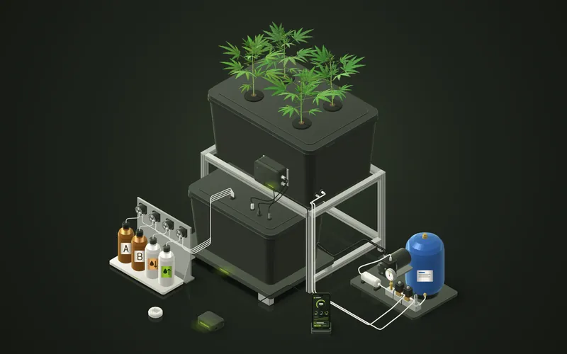
The plan from here, in order:
- Bring-up. Test each subsystem alone: relays, then sensors, then the scale, then dosing, then misting.
- Carrier board. The ESP32 goes into a proper board with the dividers and pull-ups soldered down instead of floating in the air.
- Enclosure. A sealed box above the reservoir, power on the left, sensors on the right, high-current wiring and sensor wiring crossing only at right angles.
- Labels on everything. Every cable gets a tag at both ends, like
OUT1-HPA-PUMP-A. Future us will be grateful.
Next week, in lab notes #4: every way to grow, and how one brain runs all of them.